
Medway Crematorium update
22/04/2013
Posted in Archive & Design & News
Tagged : Gravesend , Local history , Heritage Lottery Fund , George Clay Partnership , Local History , Urban Gravesham
Related posts :
History project exhibition 20th October - 1st November 2014
History Project Exhibition Opening
Progress on site at contemporary renovation and extension of historic listed home
Flitch House - Gridline K
Masterplanning underway at Gad’s Hill School
Medway Crematorium update
Phase 1 works at Medway Crematorium— east chapel extension, new cremator plant, extended car park— are nearly complete. Phase 2 ( west chapel extension ) is scheduled to complete in Autumn.
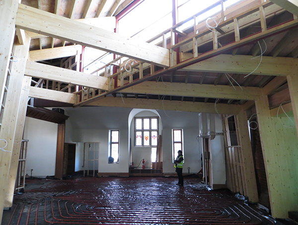
Construction is my favourite stage in the process of any project— excitement and worry in equal measure; seeing technical drawings and specifications made flesh. Did we get it right? How do we save this detail? It’s been a long winter! Blizzards; hours in the numbing cold spent discussing zinc cladding details with the roofer ( East European Muslim if I’m not mistaken ); cracking heads with Colin ( site manager ) over junction details too geometrically complicated to be worked out on paper; coordinating with Rick ( contract manager ) final items of kit to fit within the building— natural ventilation comes at a price— 700mm deep walls of louver, acoustic mitigation, actuator, ventilation damper and grille sourced and coordinated from separate manufacturer suppliers— the opposite of easy ( and in the end all hidden away from view ). But Winter is a busy period for any crematorium; we each have our own bereavements, my own included— this winter.
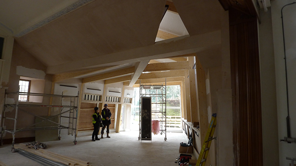
The project ticked a couple of firsts for us: first project where we proposed glulam that wasn’t value engineered out; first built Clay project where we got to apply projective geometry. The geometry of the interior of the extended chapel may look skewed but it has an iron logic to it.
The original crematorium building, designed by Sir Dawber, Fox and Robinson, was completed in 1959, during the height of the post-war crematorium building boom of the 50s and 60s. Sir Guy Dawber was RIBA president in his time; Christopher Robinson presented a paper entitled ‘Economy in Crematorium Design’ to the Cremation Society ( based in nearby Maidstone ) at their annual conference in Brighton in 1977.
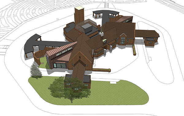
Dawber, Fox and Robinson may have designed and built the crematorium in a late Arts and Crafts style but the building betrays its modernity with a plan that looks like an X-wing starfighter; a plan that would please any geometer or process engineer.
Perfectly symmetrical ( give or take an inch or so ), the existing building has the crematory where the starfighter would have its cockpit, and an east chapel and cloister and a west chapel and cloister for X-wings. Services alternate between east and west wings at 45 minute intervals, the plan enabling delivery of services without a clash between groups of mourners.
The new works have been made necessary by two developments: one recent, one gradual. 1. DEFRA now requires that mercury ( from tooth fillings ) must be abated ( filtered ) for at least 50% of all cremations carried out. 2. Although the number of cremations have remained constant over the years, local demographic changes and changes in culture / practice in North Kent have led to larger numbers of mourners attending cremation services.
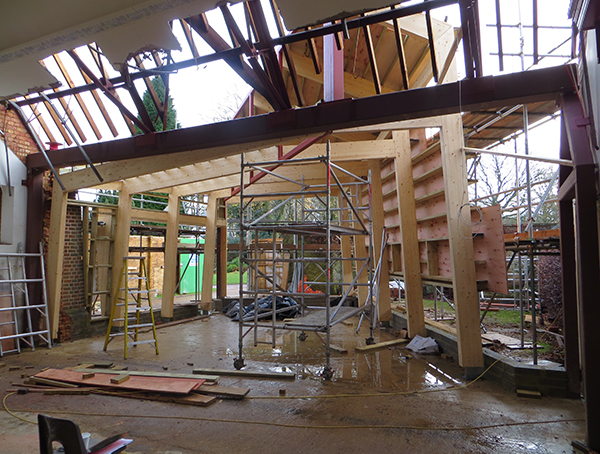
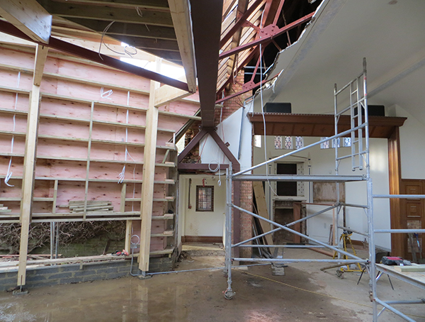
The location of mature trees and cremated remains on the site led to a decision to remove the flank wall and extend the side of the non-denominational chapels. The tapered polygonal plan of the extension to each chapel is determined by the sight lines to the coffin positioned in the apse or focal point of the chapel. So far so good, but having removed a whole wall and part of the roof down the entire length of each chapel one is left with a broken symmetry and a strange lopsided plan.
In the late ‘80s early ‘90s Barcelona architect Alfreddo Arribas ( or was it Enric Miralles in a lecture? ) described something he called ‘balanced asymmetry’. In architectural geometry we look for the centre-line or base-line for setting-out the geometric logic of a building— the building’s DNA, if you will. The geometer / architect’s challenge is to find symmetry and balance in an irregular site or set of circumstances.
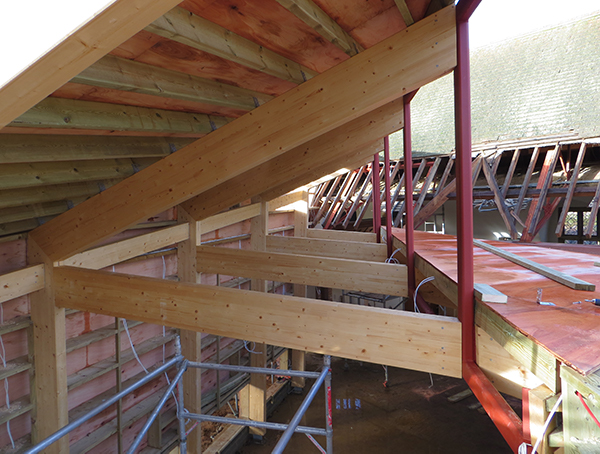
In the case of Medway Crem the original symmetry of the chapels have been so broken and the plan so skewed by the new extension sight lines that a second axis or centre-line has to be introduced, radiating from the same focal point ( coffin / apse ) as the centre-line of the original chapel. A large steel beam replaces the removed wall of the chapel; a steel Vierendeel truss springs from this beam, forming the axis of the new extension. Glulam half-portal frames spring from the top and bottom cord on either side of the truss, forming the skeletal frame of the new extension. Due to the peculiarities of the tapered sight-line plan, the glulam frame on one side of the truss rise as one approaches the focal point of the chapel, while the glulam frame on the opposite side of the truss fall. Between the top and bottom cord of the central Virendeel truss there is an opportunity to insert north-facing clerestory windows to gently light the line of sight towards the apse.
You can say the shape of the extension ‘made’ itself. We worked out what the rules were and followed them.
Brise Soleil
Camilla and I had a meeting on site with Rick to discuss the brise soliel a month or so ago, just before I had to fly to Vancouver for my mother’s funeral / wake. Rick was having trouble finding a steel fabricator to tackle the brise soliel. The structure could not be fabricated in aluminium ( specified for relatively lightness ) because welding would distort the plates too much. They would have to fabricate in steel. How to join or weld the 2- to 8-leg ‘star’ junctions of the brise soliel pattern cleanly? The brise soliel structure is large and heavy and would be difficult to galvanise, powder-coat finish, transport and erect in one piece. They would have to divide it into smaller sections. How would they fit the sections together on site? How would they make the structure of the joined up sections robust enough?
Camilla had some ideas and agreed that we’d build a large scale model to demonstrate a solution. She took charge of this while I got on the plane with our boys and flew to Vancouver.
The brise soliel originally came about because of a combination of client concerns about the design of the new chapel extension. The existing leaded stained-glass windows ( with a variation of a box diamond leaded-glass pattern ) were much loved and their removal on one wall of the chapel was a loss. There was concern that the extension design would be too ‘industrial’ looking. Although the client liked the large glass windows with views of the park at the gable-end, there was concern that that visitors and mourners to other services would be able to look through the windows into the chapel; that this would be distracting to whoever was conducting service. There was some concern about glare from the late afternoon sun into the west chapel.
Inspired by a picture of a 19th Century marble window screen from Agra ( in the V&A) we came up with the idea for a large patterned window screen fabricated from aluminium or steel. We would replicate the leaded-glass pattern of the lost windows, in blown-up scale, on this screen. A difficult piece to get right, but Camilla thinks outside the box, understands something of steel fabrication from her previous life as maker of large steel sculptures; if anyone can work out an elegant solution she can. I came back from Vancouver hit with the worst jet-lag ever and climbed the 4 flights of stairs to the office, to find the most beautiful paper card model origami in full production.
Camilla’s proposed solution is built on the foundation of 4 ideas:
Divide the structure into 6 parts, along the line where the pattern has greatest fabrication complexity ( the 8-leg star junctions ). Align these with the location of the window mullion junctions behind. Form the star junctions using a system of notched blades that slot cleanly over one another ( inspired by ‘60s slotted toy building sets ). Rationalise and break the pattern up into ‘snakes’ that slot together and form the complete pattern. Fix the 6 parts together using a secondary frame sited behind the brise soliel ( inspired by the ferramata structure of the large leaded-glass windows at St Paul’s Cathedral). The secondary frame is aligned with the location of the window mullions behind the screen to lessen its impact on the pattern.

22/04/2013
Posted in Archive & Design & News
Tagged : Gravesend , Local history , Heritage Lottery Fund , George Clay Partnership , Local History , Urban Gravesham
Related posts :
History project exhibition 20th October - 1st November 2014
History Project Exhibition Opening
Progress on site at contemporary renovation and extension of historic listed home
Flitch House - Gridline K
Masterplanning underway at Gad’s Hill School